For far too many years now, I have dreamed of building a Cafe Racer, using a 1978 Yamaha SR500 as a starting platform. The simplicity of the 500cc single cylinder four stroke engine coupled to the nimble and slim lines of the model evoke fond memories of a number of older British classic singles and twins.
I was fortunate to pick up a fully registered SR500 at a reasonable price back in April 2008. The seller had done a 'make-over' on the bike after he had purchased it in a rather sad but still running condition. The bike was missing some original components and the 'make-over' consisted of a new paint job to tank, frame, side covers and wheels. Some bead blasting and a lot of polishing was done to make the bike look good for a quick re-sale. Unfortunately, (....or fortunately it might well be!) nothing of a mechanical nature was seriously looked at and when I received the bike, several fasteners were either missing or finger tight. Some of them critical fasteners such as brake pad locking pins, front drive sprocket nut ....finger tight and not locked, kick start lever retaining bolt ....missing, and several engine mounting bolts were loose.
It was at that stage that I decided to go ahead with the metamorphosis into a Cafe racer rather than to try and restore the bike to it's original glory.
So, the following photographs will take you through the story as it unveils. Ps, it will probably be a fairly long and slow process before the last mods are done and the old SR500 is back on the road again.

This is how the SR500 would have looked back
in it's day in1978
Photos courtesy of WWW.Classicride.com.au


And many years later, ....probably about 28 or 29 at least!
The photo shows the bike before the last owner did the 'make-over'.

This was taken in April 2008 on the day that I bought the bike.
(Nice from far but I'm afraid, ...far from nice!)
The first thing that I wanted to do was tackle the issue of wheels. A lot of builders would opt for wire spoked wheels and alloy rims. For the ultimate look, these would be laced to a massive 4 leading shoe, magnesium alloy drum brake up front and a smaller single leading shoe drum on the rear. Of course you would have to mortgage the house and sell off the kids as slaves in order to finance such extravagances.
Strangely enough, I quite like the look of the old 7 spoked cast alloy wheels but they are a little 'chunky' looking so I decided to be different and give them a newer and lighter look.

This the standard front wheel as fitted to the 1978 SR500.

This is the same wheel with the centre of the spokes relieved with 3 slots.
(More about the disc brake later)

A view of the wheel on the bike without the disc brake fitted.

A view of the rear wheel without the sprocket fitted. Having shorter spokes on the rear, I opted for only 2 slots per spoke for a balanced look.

A view of both wheels on the bike. I will take better pictures once I have the bike off the lifter and parked outdoors .......one day!
Having dealt with the wheels and being pleased with the way they were looking, I then turned my attention to the brakes. I was not happy with the notoriously heavy disc rotors, nor the gorilla fist sized callipers that Mr.Yamaha used back in '78. I don't know why he chose such heavy and large units and I was going to change all that. I liked the concept of going over to a 'double disc' front end and bought a pair of FZR400 rotors and 4 piston callipers off Ebay. When I received them, the rotors were well worn past their safety limits so I was left with the callipers. If I had used the FZR rotors, it would have meant spacing them off the wheel hub and then I thought, why not just use the SR500 rotors and modify them to suit my tastes.
I drew the original SR500 rotors up in CAD and then toyed around with cut-outs, profiles and drilled hole patterns until I was satisfied with the appearance. And that was how a totally new (and different looking) disc rotor was born from an original SR500 rotor and without the need for spacers and the like.

An original SR500 front rotor - view of outside face.

An original SR500 front rotor - view of inside face.

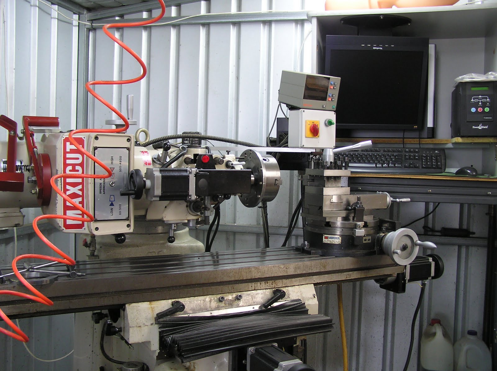
View of the rotor set up on my lathe in special holding fixture, prior to reworking of all the faces.
The Yamaha rotors are manufactured by forging or hot stamping at the factory. Because of this process, the 11 holes and the faces tend to run out of true by a considerable amount from one rotor to the next. The spokes of the rotors are also excessively thick and heavy and so I skimmed an amount off the outer and inner faces of the spokes and also skimmed the braking 'track' area to be narrower to suit the smaller width of the FZR brake pads.

View of the inner face of the rotor after skimming the spoke area.

All machining of outer face completed prior to milling the spoke profiles, new profiles and drilling the braking area.

All machining of inner face completed prior to milling the spoke profiles, new profiles and drilling the braking area.

The completed rotor with new profiled holes and drilling completed.
Incidentally it has shed about 1 kilogram in weight!

The completed rotor - inner face.
(The braking area was only skimmed as a final operation after all other machining had been completed)
Next on the list of things to make were calliper mountings for the FZR callipers. These had to be designed from scratch in order for the callipers to offer up in the correct position to the rotors. More CAD design and two 'dummy runs' in lumps of plastic before settling on a final design.

The original L/H SR500 calliper shown next to the FZR 4 piston calliper and new mounting bracket.

The FZR 4 piston calliper and new mounting bracket.

The new FZR calliper mounting in the making. View of outside face of R/H mounting.

View of inside face of R/H mounting.

View of new left hand calliper mounting - outer face.

View of new left hand calliper mounting - inner face. Both calliper mountings are identical except that the left is a mirror image of the right (obviously!).

Right hand view of FZR400 calliper, my design calliper mounting and modified SR500 rotor.

Right hand view of FZR400 calliper, my design calliper mounting and modified SR500 rotor.
(Note that fasteners are just 'roughies' I had laying around.)

SR500 Cafe
Right hand view of FZR400 calliper, my design calliper mounting and modified SR500 rotor.

SR500 Cafe
Right hand view of FZR400 calliper, my design calliper mounting and modified SR500 rotor.

SR500 Cafe
Right hand view of FZR400 calliper, my design calliper mounting and modified SR500 rotor.

SR500 Cafe
Right hand view of FZR400 calliper, my design calliper mounting and modified SR500 rotor.
It must be noted that in all of the above photos, I have not yet de-burred, polished, bead blasted, wire brushed, anodized, painted or chrome plated anything. All parts shown are as they came off my machines!
The rear disc rotor will get a very similar treatment as to that of the front rotors and I will most likely use an RZ350 rear calliper to replace the other gorilla fist!
Currently on the machines is a new steering head 'TOP TRIPLE CLAMP' to replace the stock SR500 one. It will do away with the large holes for handle bar rubber dampers and will also mount the whole instrument cluster and ignition switch about 20mm lower. These will be carried on a separate mounting plate, fixed to the underside of the new triple clamp. The new triple clamp is designed specifically to run with 'clip-on' type handle bars off the fork tubes, ie it has no handle bar mounting points.
Below is a sneak preview of what is coming!

Its on the milling machine as I write!
Well it has been a good week out in the workshop and I have managed to complete the bulk of the machining work on the new Triple Clamp. I am pleased with the way it is turning out and can't wait to fit it onto the bike with the new instrument mounting as well.
 Yamaha SR500 Top Triple Clamp - The raw lump of 5083 Aluminium prior to the first machining operation.
 Yamaha SR500 Top Triple Clamp - Pre-drilled holes for fork tubes, steering head spindle, instrument mounting plate and corners of cut-out sections. This is the bottom face of the triple clamp.
 Yamaha SR500 Top Triple Clamp - This view shows the outside profile and the bottom 'step' now completed.
 Yamaha SR500 Top Triple Clamp - Bottom face, outer profile, step-down and cut-outs now completed and ready to turn over.
 Yamaha SR500 Top Triple Clamp - Turned over and fixed to a plate with 3 screws from beneath, screwed into the new instrument mounting plate screw holes. Final machining can now be undertaken on the top face.
 Yamaha SR500 Top Triple Clamp - The swarf generator hard at work on the top face!
 Yamaha SR500 Top Triple Clamp - Top face completed. All that remains is to mill the 'pinch gaps' to the fork tube holes and to drill and tap holes for the pinch bolts.
Next, I will begin work on the instrument mounting plate pictured below.
 Yamaha SR500 Top Triple Clamp - New instrument mounting plate. View is looking at the underside of the item and the 3 small holes are for M5 screws into the underside of the new triple clamp.
Well it has been a good week out in the workshop and I have managed to complete the bulk of the machining work on the new Triple Clamp. I am pleased with the way it is turning out and can't wait to fit it onto the bike with the new instrument mounting as well.


Next, I will begin work on the instrument mounting plate pictured below.